物理的にはSEとPortableのPDSは同型のコネクタ(Euro-DIN 96-pin connectot)を使用していますが,ピンアサインは異なります.
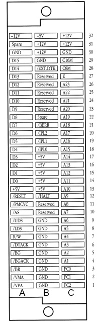
【SE PDS Expansion Connector Pinout】
(Row-Pin No:Signal nameの順)
B-1,B-2,B-3,B-4,B-5,B-6,B-7,B-8,B-9,B-29,A-30,C-30:Ground
A-13,B-13,B-14,B-15,B-16,B-17:+5V
B-30,B-31,C-31,C-32:+12V
B-32:-5V
A-32:-12V
B-10,B-11,B-23,B-24,B-25,B-26,B-27:Reserved
B-22,A-31:Spare
C-4:A1(68000 Address line, bit 1)
C-5:A2(68000 Address line, bit 2)
C-6:A3(68000 Address line, bit 3)
C-7:A4(68000 Address line, bit 4)
C-8:A5(68000 Address line, bit 5)
C-9:A6(68000 Address line, bit 6)
C-10:A7(68000 Address line, bit 7)
C-11:A8(68000 Address line, bit 8)
C-12:A9(68000 Address line, bit 9)
C-13:A10(68000 Address line, bit 10)
C-14:A11(68000 Address line, bit 11)
C-15:A12(68000 Address line, bit 12)
C-16:A13(68000 Address line, bit 13)
C-17:A14(68000 Address line, bit 14)
C-18:A15(68000 Address line, bit 15)
C-19:A16(68000 Address line, bit 16)
C-20:A17(68000 Address line, bit 17)
C-21:A18(68000 Address line, bit 18)
C-22:A19(68000 Address line, bit 19)
C-23:A20(68000 Address line, bit 20)
C-24:A21(68000 Address line, bit 21)
C-25:A22(68000 Address line, bit 22)
C-26:A23(68000 Address line, bit 23)
A-14:D0(68000 Data Bus, bit 0)
A-15:D1(68000 Data Bus, bit 1)
A-16:D2(68000 Data Bus, bit 2)
A-17:D3(68000 Data Bus, bit 3)
A-18:D4(68000 Data Bus, bit 4)
A-19:D5(68000 Data Bus, bit 5)
A-20:D6(68000 Data Bus, bit 6)
A-21:D7(68000 Data Bus, bit 7)
A-22:D8(68000 Data Bus, bit 8)
A-23:D9(68000 Data Bus, bit 9)
A-24:D10(68000 Data Bus, bit 10)
A-25:D11(68000 Data Bus, bit 11)
A-26:D12(68000 Data Bus, bit 12)
A-27:D13(68000 Data Bus, bit 13)
A-28:D14(68000 Data Bus, bit 14)
A-29:D15(68000 Data Bus, bit 15)
C-3:FC0(68000 Function Code line 0)
C-2:FC1(68000 Function Code line 1)
C-1:FC2(68000 Function Code line 2)
B-18:IPL0/(68000 Interrupt Priority Level line 0)
B-19:IPL1/(68000 Interrupt Priority Level line 1)
B-20:IPL2/(68000 Interrupt Priority Level line 2)
C-27:E(68000 E clock)
C-28:C8M(Microprocessor clock = 7.83361MHz = C16M divided by 2)
C-29:C16M(Gate Array Clock = 15.6672 MHz)
A-1:VPA/(68000 Valid Peripheral Address)(*1)
A-2:VMA/(68000 Valid Memory Address)
A-3:BR/(68000 Bus Request)
A-4:BGACK/(68000 Bus Grant Acknowledge)
A-5:BG/(68000 Bus Grant)
A-6:DTACK/(68000 Data Transfer Acknowledge)(*2)
A-7:R/W/(68000 Read/Write)
A-8:LDS/(68000 Lower Data Strobe)
A-9:UDS/(68000 Upper Data Strobe)
A-10:AS/(68000 Addres Strobe)
A-11:PMCYC/(Processor-Memory Cycle)(*3)
A-12:RESET/(68000 Reset)(*4)
B-12:HALT/(68000 Halt)(*5)
B-21:BERR/(68000 Bus Error)(*6)
B-28:EXT.STK/(*7)
*1:Supplied to 68000. For Macintosh SE, VPA space is $#0 0000 to $FF FFFF.
*2:Inserts wait states until data bus is available. Normally supplied by the gate array. Gate array generation of DTACK/ can be suppressed (put into a high-impedance state) by pulling the EXT.DTACK/ line low; this allows DTACK/ to be externally generated by an add-on device. DTACK/ is not supplied for accesses to VPA space, is held off to separate 2 successive accesses to the SCC and is held off during RAM access by video.
*3:Used to synchronize with the gate array for RAM accesses. PMCYC/ is low when RAM is available for microprocessor accesses and is high during video accesses. PMCYC/ is always high during SO.
*4:Wired directly to HALT/.
*5:Wired directly to RESET/.
*6:Generated by gate array due to SCSI access timeout.
*7:Pull low to put the gate array generated DTACK/ into a high-impedance state. The expansion board is then responsible for generating the DTACK/signal (as an output to the microprocessor, througut the DTACK/ signal line).
*The Mac SE Support Pagesより抜粋